 Midnight Lite
The ferrofluid add-on board is designed, checked and ordered. Five boards are being made and assembled at JLCPCB right now, so here’s what’s on it before the real thing turns up.
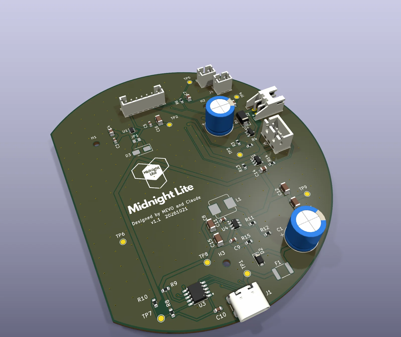
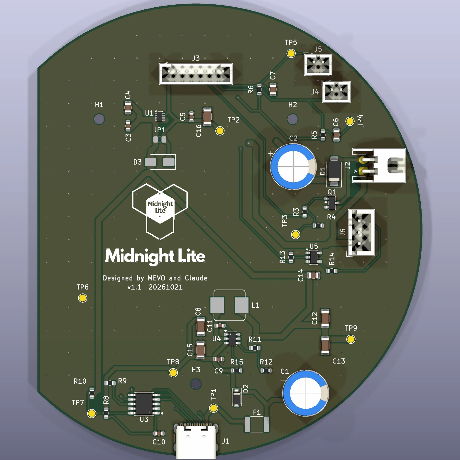
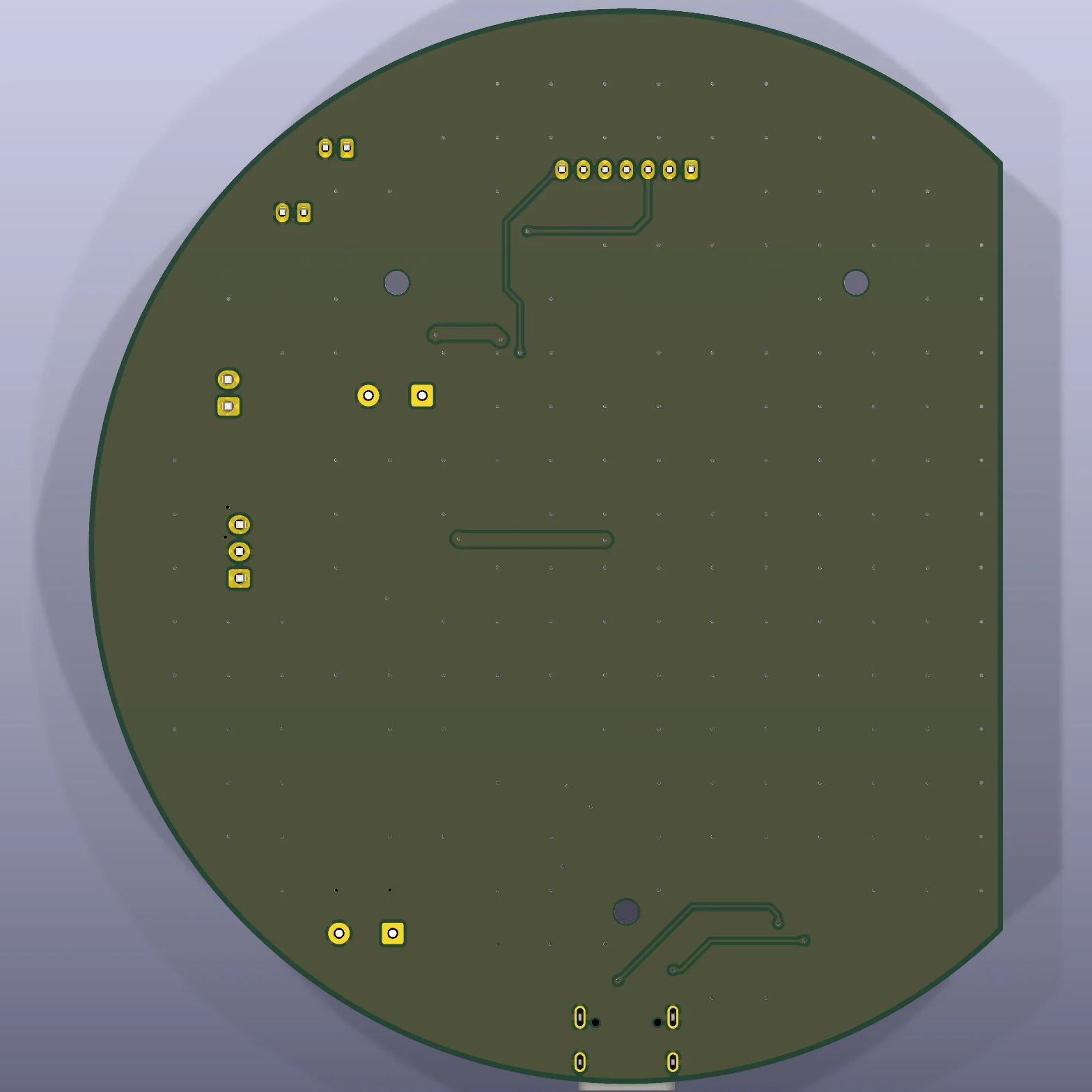
These are KiCad renders, not photos. Photos come when the boards arrive.
What the board does
It’s a 100 mm round board (with one flat edge) that sits under a Seeed ReSpeaker voice board with a XIAO ESP32S3. Its job is everything the ReSpeaker can’t do on its own:
- Power. USB-C in. A CH224A chip asks the charger for 9 V over USB Power Delivery, and a TPS565208 buck converter turns that into a 5 V rail good for up to 5 A.
- Feeding the ReSpeaker. A TPS2116 power switch passes 5 V to the ReSpeaker and blocks power from flowing backwards if its own USB-C is plugged in too.
- The magnet. A MOSFET switches the electromagnet under the bottle at about 25 kHz, from one ESP32 pin. That’s what makes the ferrofluid move. The coil takes roughly 0.5 to 1 A.
- Not cooking itself. Two temperature sensors: one on the coil, one on the glass.
- Light. A level shifter so the ESP32’s 3.3 V signal can drive an addressable LED strip that backlights the bottle.
- One cable. A 7-wire JST-PH cable links the board to the XIAO. The coil and LED current never go through the ReSpeaker.
How it was checked
Before ordering, the design went through:
- ERC and DRC in KiCad: zero errors, zero unconnected pads.
- A pin-by-pin check of the netlist against the design table: 140 pins, 0 mismatches.
- Every chip’s pinout against its datasheet, because a wrong symbol is the classic first-board mistake.
- A ground check. DRC only proves every pad is connected somehow. A small script refills the ground pours and lists each separate piece of copper with its vias. It caught the buck converter’s ground pin hanging off a 0.2 mm track to a single via, which DRC was perfectly happy with. That check now runs on every board before export.
The parts swaps on order day
Two parts were out of stock when it came to ordering:
- The CH224K became a CH224A: same pinout, still in stock.
- The USB-C connector changed to an HRO TYPE-C-31-M-12.
The copper didn’t change, so the board is still the same design, now called v1.1.
Lesson learned: JLCPCB’s assembly stock is not the same as the LCSC shop’s stock. Check the assembly parts library.
JLC’s placement preview also showed five parts rotated wrong (90° or 180° off). Those were fixed by hand in the preview before paying. Always look at that preview.
The order
- JLCPCB: 5 assembled boards, US$63.13 with UPS shipping.
- Mouser: AU$220.07 for the hand-soldered parts and connectors for all five boards, plus the ReSpeaker, 2 m of NeoPixel strip and spare capacitors.
How it was made
I designed this with Claude (Anthropic’s AI) as an assistant. It drafted the schematic in KiCad, checked parts against datasheets and stock, and ran the checks. I made the calls and routed the board myself. Hence “Designed by MEVO and Claude” on the silkscreen.
What’s next
Bring-up when the boards arrive, in a set order:
- Check for shorts.
- Power: 9 V from the charger, 5 V out of the buck.
- The ReSpeaker feed.
- The coil driver and temperature sensors.
- The LEDs.
Each step gets tested before the next one is powered, and the results go in the next post.